Perkin Elmer model 337
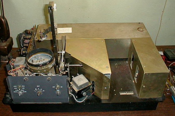
Image 4: Top cover removed from the instrument showing the three enclosed compartments: source compartment right front, rotating sector mirror/chopper compartment middle front and the monochromator and detector compartment in the back (long rectangular box).
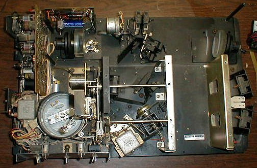
Image 5: view from the top with all the covers removed. See US patent 3,144,498 for details and operation of the instrument. The filter changer mechanism is positioned after the exit slit of the monochromator in the picture below (in back and to the left of the diffraction gratings) and is shown positioned before the monochromator in the patent. US patent 2,888,623 gives the details of the servo mechanism and some of the details of the electronic schematic. The detector appears to be the one disclosed in US patent 2,526,491. Note that these three patents all assigned to the Perkin Elmer Corporation are expired and in the public domain.
See also Optics - mirror replacements