Perkin Elmer model 337
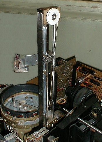
Image 6: the belt drive assembly for the rotating sector mirror/chopper assembly is shown. The top reed relay (housed in long glass tube connected to the orange wire) can be seen inside of the black square metal frame which supports the mirror axle bearings. The lower reed relay (not shown) is connected to the white wire. A semicircular magnet on the mirror axle alternately opens and closes the reed relays as it rotates (one closes while the other opens). The reed relays are used in the demodulator/demultiplexer in the servo amp shown in the electronic schematic (link on the electronics page).
Image 7: reference beam wedge attenuator (long arc shaped copper colored slotted sheet metal) is controlled by the servo mechanism through the rod shown in the center of the picture. As the spectrum is scanned the reference beam attenuator is adjusted by the servo mechanism so that the energy in the reference beam is equal to the energy in the sample beam (optical null). The semicircular rotating sector mirror/chopper can be seen in the center right of the picture. As the mirror rotates the sample beam is passed during one half cycle and the reference beam is reflected during the other half of the cycle (resulting in time division multiplex signals: alternating reference beam/sample beam signals at 13 cps). After the rotating sector mirror/chopper both beams are combined into the same path which goes into the monochromator and then to the detector. The signals from the detector are amplified and demodulated by the preamp and servo amp which drives a two phase servo motor which controls the reference beam attenuator and the position of the chart recorder pen. The sample beam attenuator (shorter slotted copper sheet metal) can be seen behind the rotating mirror assembly. The position of the sample beam attenuator is manually adjusted through the rod on the right which is connected to a threaded rod and lever mechanism controlled by a knob on the front of the spectrophotometer. Manually adjusting the sample beam attenuator allows positioning of the pen on the chart paper before a spectrum is scanned. See US patents 3,144,498 and 2,888,623 for further details.
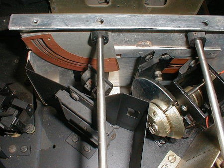
Image 8: Two phase servo motor and drive arrangement which controls the reference beam attenuator and recording chart pen drive. The rod at the pivot of the arc shaped pulley is the same rod shown in Image 2 above which controls the position of the reference beam attenuator. See US patent 2,888,623 for explanation.
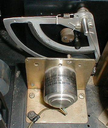
Image 9: chart recording pen drive assembly with cover removed (controlled by servo motor and drive assembly in synch with the reference beam attenuator).