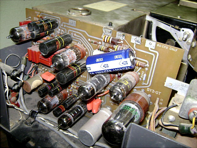
Image 15: Amplifier PCB/servo amp ( includes added 82uf 450V capacitor across 350V unregulated power supply).
Perkin Elmer model 337
Electronics
Electronic schematic:
Schematic1-1200dpi.pdfElectrical Interconnections:
ElectricalInterconnections.pdfPreamp and servo amp circuit boards:
PreampNAmp.pdfVoltage and resistance charts
: VoltageNResistanceCharts.pdfPerkin Elmer 137B manual:
http://www.scribd.com/doc/144399735/PE137B-ManualPerkin Elmer 337 brochure:
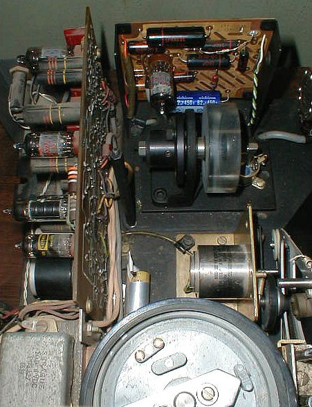
http://www.scribd.com/doc/144401610/Pe-337-Brochure Schematic, charts and diagrams in gif format (same as above)Image 14: one tube preamp shown at the back of the instrument behind the detector and the servo amp on the left in the picture. The servo motor and drive mechanism can be seen in the center right of the picture.
Image 15: Amplifier PCB/servo amp ( includes added 82uf 450V capacitor across 350V unregulated power supply).
Repairs and Modifications
(may be updated later)
The following tests, repairs and modifications were done on the Perkin Elmer 337 shown in the pictures. This may serve as a guide for others interested in working on this type of instrument. I was able to find a service manual for a Perkin Elmer 137 (prism version) which is related to the 337 (grating version). By comparing the schematic from the 137 manual and 337 circuit boards, it appears that the circuit boards used in both the 137 and 337 are the same.
1) The power cord was partially disassembled and checked with an ohm meter for shorts and open circuits.
2) The electrolytic capacitors on the preamp board and servo amp board were checked in circuit using an ohm meter (regular battery powered, not high impedance). This procedure can often be used to find electrolytic capacitors that have a high leakage or are shorted, but isn't completely reliable for testing capacitors for leakage, loss of capacitance, etc. due to age and/or defects.
3) The power cord was connected to the instrument and the switch was turned on which resulted in the instrument failing to power up. The problem was found (using an ohm meter) to be the power switch which was replaced by a new one.
4) After replacing the power switch, the instrument was turned on and over time the tube filaments and the source lit up, a humming noise was evident and the sector mirror motor didn't turn (due to dirty bearings). The humming noise was found to be caused by the capacitor in series with the servo motor. Checking the capacitor with an ohm meter showed that it had a high leakage (resistance was about 50K after being charged up). This was replaced with a 400 VDC capacitor and then later replaced with two 220 VAC high current polypropylene motor capacitors placed in parallel (best I could find on Ebay at the time). After the sector mirror motor and belt drive system was lubricated and turned by hand, it was found that the motor would start and turn by itself when the instrument was turned on.
5) A small flash light was used to check for alignment of the mirrors in various places in the instrument. After using this crude technique it was judged that the mirrors were aligned well enough for the instrument to work if all the electronics were working properly.
6) After the servo motor capacitor was replaced and the sector mirror system fixed the instrument was turned on and was found to be unresponsive even with the slits open all the way. Blocking the sample or reference beam in a working spectrophotometer normally causes the chart recorder pen to be deflected. Blocking these beams caused no response. A note was found on top of the monochromator cover which said "waiting for T.C." which apparently meant the thermocouple detector needed to be replaced. The original detector was then replaced with a detector from an old Perkin Elmer model 710B IR spectrophotometer (with solid state electronics) which is almost the exact same size and shape as the model 337 detector. After this, the 337 worked to some extent (blocking beams caused pen deflection), but some instabilities were noted which are discussed below. The 710B detector appears to be somewhat weak, too. Even after the instrument had been worked on further (details discuss ed below) the best spectrum could only be obtained with the slit control knob turned to 8 or 9. Note: both the Perkin Elmer models 710B (with mostly transistor (includes one op amp IC) electronics) and model 337 use an impedance matching (step up) transformer between the thermocouple detector and the preamp. The detector appears to be the one disclosed in US Patents US Patent 2,526,491, US Patent 2,526,492 and US Patent 2,652,442.
Possible sources for spectrophotometer detectors http://www.eoc-inc.com/drc_thermopile_detectors.htm and http://www.monoinstruments.com/detectors.html
One stability problem that was never really solved is that when the instrument is first turned on the chart recorder pen wants to move to one side of the chart recorder and appears to put stress on the motor and chart drive system. This can be compensated for by adjusting the reference voltage balance (chart recorder pen balance) control R223 a couple times to move the pen to the center of the chart recorder while the instrument warms up sufficiently to remain stable. I also recommend that the gain control R201 be turned down when the instrument is first turned on and then adjusted to its optimum level after the instrument is warmed up.
7) A hum balance control was added. This comprises a 100 ohm potentiometer placed across the filament voltage supply with the positive bias wire (connected at one end to the point where R242 and R243 meet and the other end originally connected to one side of the filament voltage supply) disconnected from the filament voltage supply and then soldered to the center tap of the 100 ohm potentiometer (see schematic, link to file Schematic1-1200dpi.pdf at top of page). The design I used is to support the potentiometer with two short heavy pieces of solid wire (14 gauge) soldered to each end of the potentiometer and then to circuit board traces which supply each side of the filament supply voltage. The solder was melted with a soldering iron on the circuit board where R242 and R243 meet and one lead from each resistor was pulled up out of the circuit board and soldered together along with a length of wire. A hole was drilled in the circuit board (between traces) and the wire was passed through the hole and soldered to the center tap of the potentiom eter to supply the positive bias to the center tap. I recommend supporting the potentiometer using a standoff of some kind rather than soldering conductors from the potentiometer to the circuit board traces. Over time the traces start to pull away from the circuit board. I used this design so I could quickly install the hum balance control for testing. After the hum balance control was installed, the instrument was turned on and warmed up a while, the reference voltage balance control R223 and gain control R201 were adjusted and oscilloscope leads were connected to test point S on the servo amp board and ground. 60 cycles was evident on the oscilloscope initially and it was found that it could be eliminated by adjusting the hum balance control.
8) A solid state rectifier was installed where the 5Y3-GT rectifier normally is. This gave an unregulated DC voltage higher than 350 volts (between R233 and V208 in the power supply). When this was substituted with a 5Y3-GT, the unregulated DC voltage became 350 volts and the 5Y3-GT was left in. Solid state diodes are shown in the schematic for V203 (detector diodes) and a 7 pin can was found in the V203 socket on the servo amp circuit board. The 7 pin can was tested with a volt-ohm meter set to test diodes and was shown to contain two silicon diodes. Since vacuum tube diodes (70 and 71) are shown in figure 4 in US patent 2888623, the 7 pin can was substituted with a 6AL5 vacuum tube twin diode (same pin diagram) and the filaments of the 6AL5 lit up when the instrument was turned on and the instrument worked using the 6AL5. Apparently the circuit board was originally designed for use with a vacuum tube twin diode like the 6AL5. Its known that solid state diodes need a certain amount of voltage to foward bias the diodes (0.3 volts for germanium and 0.6 volts for silicon). Vacuum tube diodes are foward biased just above zero volts, so operation of the spectrophotometer may be affected by the type of diodes used in the detector. Because of this it may be possible, theoretically, that the instrument has better resolution with vacuum tube diodes compared with solid state diodes. When using the 6AL5, the instrument seemed to be less stable due to noise in the instrument, therefore when using a 6AL5, the instrument should be maintained and/or modified to reduce noise as much as possible. As the instrument was worked on (described on this page), the stability improved and reasonably good spectra could be recorded using the 6AL5 in the instrument.
I made a web page showing pictures of the original detector from the Perkin Elmer 337 and one from a Pye Unicam IR spectrophotometer. The Pye Unicam was made later and I figured that the detector might be more sensitive than the Perkin Elmer detector and could be adapted for use in the Perkin Elmer 337. The Pye Unicam detector has a built in preamp and a power supply needs to be set up in the 337 to power it. A voltage divider comprising a 220K resistor and a 15K resistor between the 210V regulated supply and the regulated ground would provide about 13 volts. Compare to R242 and R243 in the Schematic (1200 dpi). Maybe I could power the Pye Unicam detector from that and have the signal from the detector go into the 500K pot gain control R201 (tube preamp disconnected).
9) The 12ax7wxt in the preamp circuit was replaced with an Electro-Harmonix 12ax7eh which has a specially wound filament for reducing hum. It was found that the 12ax7eh wouldn't work unless it was provided with a grid leak resister of several megohms value (3, 4.5 and 6 megohms was tried) on the first triode stage. This gave reasonably good performance and seemed to be as good as or better than a lot of the 12ax7wxt tubes in my collection when comparing them in the preamp circuit. The use of a floating grid for a WE403B pentode based preamp for the Perkin Elmer model 21 is discussed by Liston and White in J. Opt. Soc. Am.1. The Perkin Elmer 337 uses a triode based preamp and is designed with a floating grid on the first triode. According to the article, the use of a floating grid provides a self-adjusting bias to the optimum point and makes the selection of input tubes and the adjustment of filament temperature far less critical than with the previous circuits.
1) "Amplification and Electrical Systems for a Double Beam Recording Infra-Red Spectrophotometer" M. D. Liston and J. U. White Journal of the Optical Society of America, January 1950 pages 36-41