Espey 200 am/fm radio and Pilot 100 stereo demodulator
I got an Espey model 200 am/fm radio (fm is originally mono) from an antique store in the 1990s and recently connected it to a Pilot 100 stereo demodulator. I had to replace the capacitor can in the Pilot 100 because of hum. I modified the Espey 200 according to an article in Electronics Illustrated (April 1959 pages 32-35) on creating an mpx jack for mono tubed FM radios. The Espey has a ratio detector which I connected to the jack. I also put in an RF connector for connecting it to a piece of coax cable that goes to the antenna RF preamp power supply (See http://antiquesci.50webs.com/WMUC.htm )
The Espey uses a 6BE6 pentagrid mixer tube in the front end. It sounds less distorted than my Dyna FM-3.
Espey 200 schematic
Pilot 100 schematic
http://pacifictv.ca/schematics/pilot100data.pdf
US 3175041 Fm stereo demodulator using time division switching
Pilot Radio Corp.
See Figure 10
US 3175041
More info on pentagrid mixers
Quote:
As the number of stations increased and the power levels also increased; receiver performance had to improve. The pentagrid converter, such as the 6BE6 tube (British EK90 valve), was introduced which was optimized for mixer performance. This included the isolation of local oscillator and input signal as well as allowing the first grid and cathode to work in an oscillator configuration. These tubes allowed a closer approximation to the multiplication of the two sine waves which produced fewer spurious mixing products.The British used a 7 grid tube with similar multiplication properties in FM broadcast receiver demodulators. They picked signals off the primary and secondary of the last IF double tuned transformer (which were 90 degrees out of phase) and multiplied them.
http://www.analog-rf.com/mixer.shtml
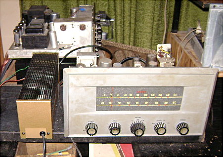
Pilot 100 (left) and Espey model 200 (right) (Fisher x101 stereo amp in the background)
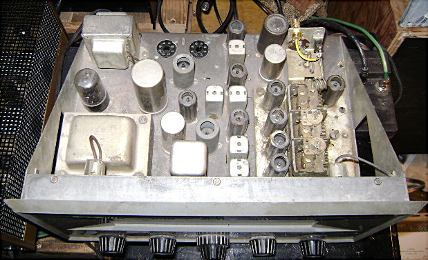
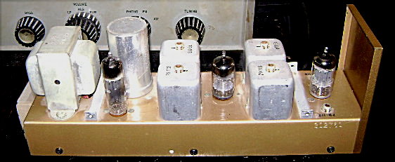
Epsey 200 top with 6V6GT tubes removed (octal sockets)
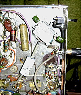
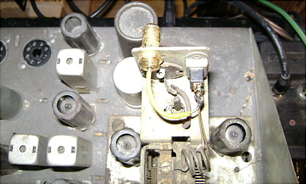
RF connector added to Espey 200
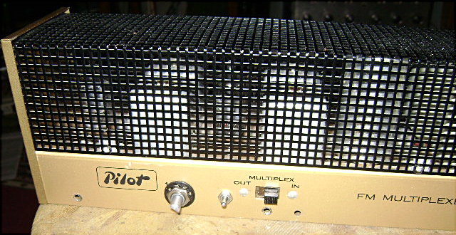
Pilot 100 stereo demodulator
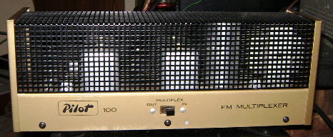
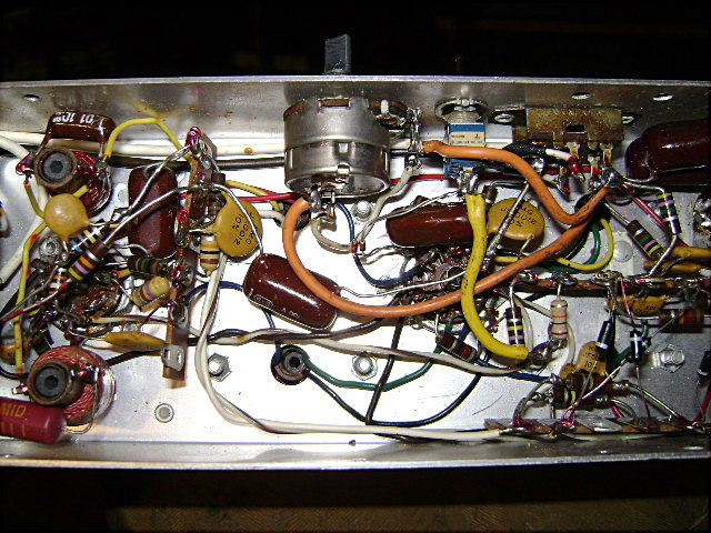
Pilot 100 stereo demodulator open
Link to Electronics Illustrated April 1959 pages 32-35

19 kHz limiter for stereo demodulator
I got the idea of putting a 19 kHz limiter in my Pilot 100 stereo demodulator from these three patents.
US 3235663 Fm stereo multiplex receiver having limiting means in the pilot channel
US 3287501 Multiplex detector circuit
clipper 35
US 3270138 F. M. stereophonic receiver having noise prevention means in the pilot circuit
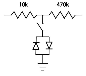
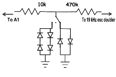
The simplest modification seemed to be to use antiparallel diodes across the signal path to clip positive and negative peaks outside the +/- 0.6 volt range (for two silicon diodes). I put the limiter at point A in the schematic.
http://members.shaw.ca/pacifictv5/pilot100.jpg
The limiter includes a 10k resistor between tank circuit A1 and the 470k resistor with the antiparallel diodes connected between ground and the connection point between the 10k and 470k resistors. I put a switch in the circuit to switch the diodes in and out of the circuit to compare the effect with and without the limiter. WMUC (88.1 MHz) broadcasts with 10 watts of power and when the Pilot 100 is set to stereo, usually a grumbling splatter sound can be heard during silent passages which seems to be from interference from nearby stations, like NPR on 88.5 MHz and probably other stations. Sometimes when WMUC is off the air I can hear a lot of noise at 88.1 MHz which sounds like other stations bleeding over into that frequency, as well as another distant station on 88.1 MHz. Switching the diodes into the circuit essentially causes the grumbling splatter sound to disappear, but some noise ccan still be heard at a lower level during silent passages. Its a distinct improvement. Before this, I put a 500k pot having a switch in the Pilot 100 between the slide switch stereo outputs as a blend control which can be switched on and off and adjusted between stereo and mono. Blending the left and right outputs tends to reduce noise since the stereo noise is out of phase in both channels.
------------------------------------------
Here's some other examples I found which use antiparallel diodes for limiting signals.
US 3250919 Amplitude limiter using tunnel diodes
US 3448359 SELF-ADJUSTING COMPENSATOR PREFERABLY FOR MEASURING RECORDERS
antiparallel diodes 32 (fig. 2)
US 3102991 Sonar equipment for single-transducer operation
US 4357690 Switch circuit for exciting ultrasonic transducer elements
http://www.swtpc.com/mholley/PopularElectronics/Popular_Electronics.htm
scroll down to and click link to the M/M/M Instrument Amplifier
http://www.google.com/patents?hl=en

The pictures below show the limiter circuit and modified Pilot 100 with the pot and limiter switch to the left of the slide switch.
Update July 19, 2012
I added a second diode network to the 19 kHz limiter which clips at a higher voltage. An On-Off-On switch was also added to switch either diode network in or out of the circuit. The switch is positioned to get the most stable operation and best signal to noise ratio.
Dynamic limiter for Espey 200
I tried adding another limiter, this time in the Espey 200 receiver. I tried putting a modified anti-parallel diode dynamic limiter based on limiter 55 in figure 1 in
US patent 3080453, at the control grid of the 6AU6 2nd FM IF amp.
I put a 2.5 mf 220 VAC polypropylene capacitor between the grid of the 6AU6 in the Espey and the dynamic limiter to block DC and prevent it from affecting the bias on the control grid of the 6AU6. I also put a switch between the dynamic limiter and ground so I can switch it in and out of the circuit. The dynamic limiter tends to affect the tuning of the IF transformer a little bit which I had to tune after putting it in the radio. It makes a big difference with weak stations, less noise and better stereo image. Both the dynamic limiter in the Espey and the 19kHz limiter in the Pilot 100 are needed with weak stations to get the best results.
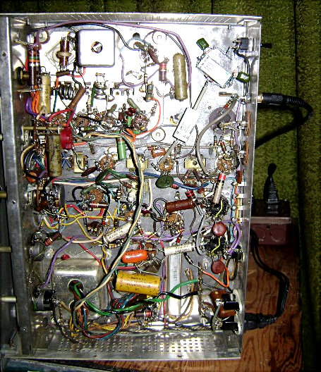
Espey 200 with dynamic limiter shown below (two big white 2.5 mf polypropylene capacitors, two green .047 polystyrene capacitors and two hard to see silicon diodes and 8.2k resistors connected to a switch in the back of the Espey 200)