Inside the Perkin Elmer model 700 Spectrophotometer
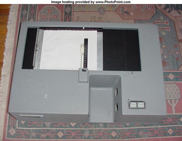
Top view
Note chart recorder, sample area and the scan and power buttons to the right of the sample area.
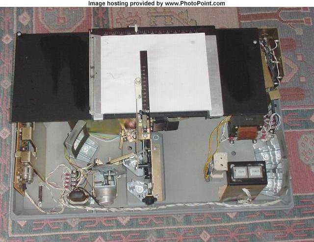
Top view with top cover removed
The source housing can be seen just to the left of the scan and power buttons. The source is connected to yellow wires leading to the multitap transformer. Two source mirrors can be seen on the far right. The partition can be seen in the middle front of the instrument which includes the sample and reference beam apertures, and has mounted on it, the adjustable sample beam comb, reference beam servo comb (attenuator), chart recording pen drive and the servo motor for controlling the position of the servo comb and recording pen. To the left of the partition are a couple of mirrors, the rotating sector mirror and motor and a spherical mirror. The servo amp circuit board can be seen on the far left.
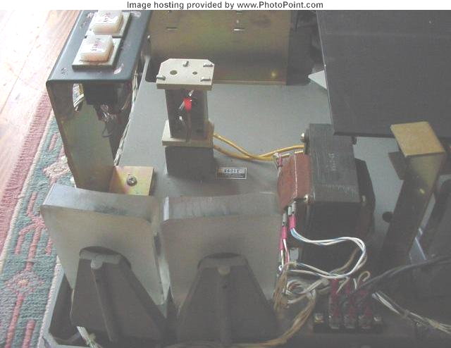
Nichrome coil heater (source), mirrors, scan and power buttons and multitap transformer, view from the right of the instrument
See also
PE model 700 Optical Schematic
Infrared Spectrophotometers