---------------------------------------------------------------------------------------------------------
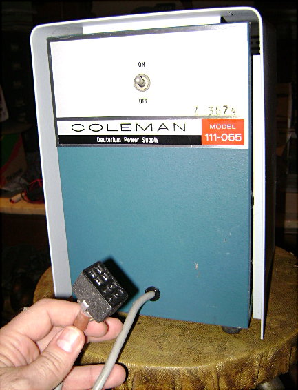
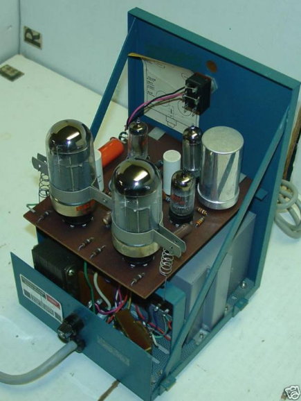
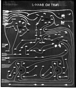
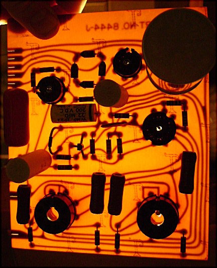
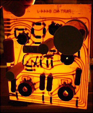
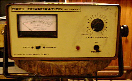
Testing the Oriel 6310 power supply. Front, back and inside shown below.
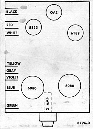
Oriel model 6310 deuterium lamp power supply manual
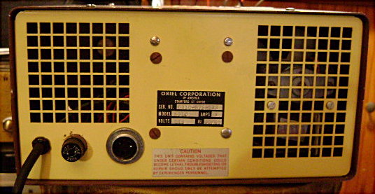
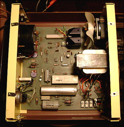
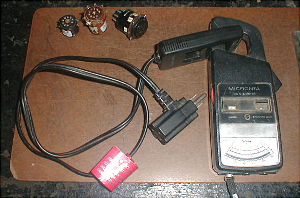
I opened up the power supply to do a visual check and found no damage and nothing burned up and decided to try turning it on while using a clip-on type ammeter (first picture below) to check the current used by the power supply to make sure it wasn't drawing too much current which might happen if something was wrong with it. I made a variable dummy load using a 2K potentiometer in series with two 2 watt 270 ohm resistors each soldered to an aligator clip. Without the dummy load connected the voltage read about 450 volts on the front meter and when connected to pins 1 and 3 (pin 1 high voltage anode supply (cable red wire), pin 3 Q103 side of filament supply (cable white wire)) the voltage was around 175 volts (an Amphenol 91-MC3M connector is connected to the other end of the cable which connects to the socket on the back of the 6310). Adjusting the dummy load 2K pot and the lamp current control on the front had some effect on the voltage and current readings, but not too much. The voltage stayed around 175 volts and the current varied between about 0.15 to 0.25 amps. The relay circuit seems to be working which is evident from the change in voltage from 450 to 175 volts when connecting the dummy load. I want to try connecting a 25 watt D2E deuterium lamp to the Oriel 6310, but I'm not sure if the control will lower the voltage to the 95 volts it needs so I was planning on connecting a 50 watt potentiometer in series with it. It might be best to check Q103 to make sure its good, too.
---------------------------------------------------------------------------------------------------------
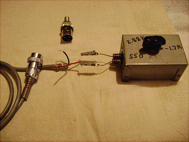
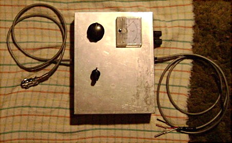
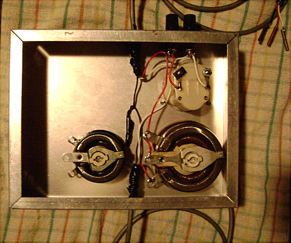
I tried making an interface with a 500 ohm (100 watt) potentiometer arranged as a variable resistor with a 500 volt voltmeter at the output for measuring the voltage between the anode and filament of the D2 lamp. The 500 ohm pot is designed to be in series with the high voltage from the power supply and the anode of the D2 lamp. Compare to fig. 2 (page 595) here AO17-4.PDF which uses a 1k 100 watt resistor between the 400 V battery and anode of the lamp.
Some brass tubing designed to fit onto the lamp terminals are soldered to the wires. The smaller potentiometer isn't connected to anything right now.
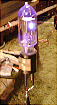
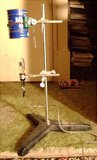
I got the lamp working a couple weeks ago and just now got around to taking pictures of it. I put the D2E lamp on a stand. Brass tubing is soldered to the wires which connect to the lamp terminals. Heat shrink tubing covers the brass tubing for electrical insulation. The coffee can is held by a clamp and can be lowered over the lamp for safety and to block short wave UV which is bad for your eyes and can cause sun burn, too. The lamp takes a couple minutes to warm up before it ignites. The high voltage across the lamp is about 300 volts before the lamp ignites (its 450 volts without a load) and drops to about 80-90 volts when the lamp ignites. I had the interface between the Oriel power supply and the lamp and after a couple minutes turned to the potentiometer to 0 ohms. The interface probably isn't necessary with this lamp. The lamp current control is set at the start position, too. After the lamp ignites the current control can be adjusted. The lamp seems to run OK at about 80-90 volts and about 0.2 to 0.25 amps.
The lamp glows blue when ignited. Some D2 lamps glow orange. I'm not sure what the difference is.